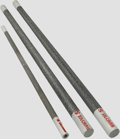
Due to their high density of 2.4gms/cc (or more), the Alpha Rod Elements are designed to give superior performance. This gives the element exceptional characteristics and additional strength.
Various kinds of special surface coatings are provided onto the Alpha SiC rods. These vary from glass coatings to Chemical Vapor Deposition (CVD) coatings depending on the area of application. We provide different coatings for assaying furnaces, coatings to be employed in very high vacuum applications and coating to be employed in reducing atmospheres.
Do get in touch with us and let us know about your applications and atmospheres in which you wish to use the heaters and we will suggest the right surface coating for the application.
The operating temperature of the Alpha Rod Elements can go up to 1550°C in an oxidizing atmosphere, or inert gas atmospheres of argon or helium. in a reducing atmosphere, the maximum obtainable operating temperature is 1350°C.
The Alpha Rod elements increase in resistance gradually, with use. This characteristic of increasing resistance is called Aging. Aging is a function of the following:-
There are no restrictions on the mounting positions of Silicon Carbide Heating Elements. Horizontal and vertical positions are the most common positions. The Heating elements must be mounted with extreme caution to ensure that the elements are not mounted in tension. There should be adequate allowances provided for the furnace and elements to expand and contract without any hinderance. When the elements are mounted vertically, it must be made sure that they are supported on the lower end by electrically insulated supports. It is ideal for the Silicon Carbide Elements to have their heating sections centered in the furnace chamber so that no portion of the heating section extends into the furnace wall. For heat to be radiated properly and the temperature to be maintained, a conical or truncated cone-shaped recess inch deep is provided on each interior wall where the element passes through.
The resistance of Ultra-Spiral/Alpha SiC rod Element varies with temperature as detailed in the below table. From relatively high value at room temperature, it falls to a minimum at about 800℃ and then gradually rises to its maximum operating temperature.
The resistance value at 1400℃ will approximately be 10% more than its value at 800℃. The voltage across the element and the current passing through it should be measured at about 800℃ to determine the resistance (V=IR)
| Mean Furnace Temperature(Degrees Centegrade) | 1500 | 1450 | 1400 | 1350 | 1300 |
| Maximum Surface Loading(W/cm²) | 3 | 4 | 4 | 5 | 6 |
Alpha Ultra Spiral/Alpha Rod elements can operate in air(oxidizing) at the furnace temperature of up to 1550℃. Elements can also be used in a reducing or neutral atmosphere but at lower temperatures. The recommended operating temperatures for Ultra Spiral/Alpha Rod Elements in different process atmospheres are as follows.
| Atmosphere | Maximum Element Temperature(C) | Comments |
|---|---|---|
| Air | 1550 | |
| Vacuum | 1000 | Depends on degree and period of application. Use unglazed elements for extended use in vacuum |
| Pure Nitrogen | 1050 | |
| Hydrogen | 1200 | Unglazed elements may be required |
| Exothermic Gas | 1250 | Unglazed elements may be required |
| Endothermic Gas | 1250 | |
| Hydrocarbons | 1250 | Periodic burn – off of carbon deposition may be required |
(Note that element temperatures are indicated and that these may be Considerably higher than the furnace temperature)
The operating temperature of the elements is mainly dependent on two things-(a)the furnace temperature and (b)the specific element loading, normally expressed in watts per square centimeter(inches) over the hot zone length.


Ultra-Spiral/ Alpha Rod elements are preferably operated in air or other oxidizing atmospheres, as other gases tend to react with the element material or the protective glaze, therefore reducing the life of the element. It is recommended to consult the manufacturer if the use of Ultra-Spiral heaters in corrosive atmospheres
Water vapor too has an adverse effect on ‘Ultra-Spiral / Alpha Rod heaters, it increases the oxidization of the material and hence the aging rate. The furnace should be completely dried before the elements are installed but if the requirement is to use the elements for drying, then it should be made sure that the furnace is well ventilated, and no build-up of steam should be allowed.
Other process vapors can also have an adverse effect on the element of life. It can either chemically attack the silicon carbide and the protective glaze or condense in the element support holes causing restriction and eventually breakage. Most alkali vapors will have a detrimental effect, halogen gases, metal halides (e.g. Fluxes in aluminum furnaces) and also most of the metallic oxides.
To minimize any attack an efficient extraction system should be incorporated to reduce the volatile concentration in the chamber to an acceptable level. This will also encourage an inflow of air over the element cold ends and minimize any condensation at these points.
The elements must be accurately positioned in the furnace to ensure that the hot zone does not enter the element support holes. It is important to ensure that elements are free to move in all directions and mounting holes must be aligned and sufficiently large to prevent restriction, for expansion during the hot condition.
Special lead-in sleeves are available for each size of the element. They should be fitted from the outside of the furnace in holes bored to a diameter which will ensure a loose fit. Sleeves should never be cemented into position. If sleeves are not used then the element support holes should be about 3-6mm large than the element diameter for sizes up to 18mm about 8-10mm for larger sizes. For exceptionally thick furnace lining and where there is a possibility of volatiles condensing on the cold ends, a fairly large hole diameter should be used and the elements centralized by supporting them on a small ceramic fiber pad under cold end.
 Special lead-in sleeves are recommended for use with Alpha ultra single-ended elements to provide the correct alignment and support required. These sleeves should be of a loose fit and not cemented into positions. Type Alpha ultra single-ended Elements can be mounted horizontally or vertically, projecting up or hanging down. The terminal assembly should be outside the furnace structure to keep it as cool as possible. No Portion of the spiral heating section should extend into the refractory wall. The element should be mounted in a high Die-electric lead-in sleeve to prevent possible shorting of the terminal ends because full element voltage exists along the entire length of the Terminal.
Accessories Silcarb manufactures a range of element connections To suit its Ultra-Spiral /Alpha Rod Elements

A variable voltage source is necessary to provide power input to the heating elements to offset the drop in rating due to the aging of the elements with use. A transformer (tapping or continuously variable) or a thyristor drive would serve the purpose. However, it is recommended that a 100% voltage reserve be provided to ensure the maximum life from the heating elements. In the case of a stepped output tapping transformer, it should be ensured that adequate taps are provided. It is recommended that a minimum of 8 Stepped outputs or taps be provided to ensure that the elements are not drastically overloaded While changing from one tap to the next higher one.
Alpha Rod/alpha ultra spiral should be spaced at a minimum of 1 diameter between element centers and the refractory lining. A clearance of at least 2.5 diameters, should be allowed between the element centers and the wall, but it may be necessary to increase this if uniformity of heating is required, especially if the distance between adjacent elements is large.
A = ( 1.5 x D) = Minimum spacing between component centre & adjacent refractory
B = ( 2.5 x D) = Minimum spacing between adjacent element centres
C = ( 1.5 x D) = Minimum spacing between component centers & hearth plates or work
D = component Diameter

Note: if under heating is to be used, then the hearth plates should have good thermal conductivity. Suggested material being Silicon Carbide.
Silcarb today is one of India’s leading manufacturer of Silicon Carbide Elements. Silcarb has been manufacturing heaters now in Bangalore, India for the last four decades. Silcarb is known for its high quality and fast response time to customer needs. Due to high volumes of production, Silcarb is also able to price its products competitively. Silcarb is constantly innovating to reduce energy consumption for both its customers & its own in-house production facilities.